Technical informationCaution of corona discharge test of transformer and coil
Well, this time we will explain the wiring that you make mistakes when using the corona discharge tester. If you start measuring partial discharge or corona discharge, we think that it will be helpful if the results are unstable and strange.
Ⅰ. Test between core and coil
In Figure 1-1, a high voltage is applied to one side ① of the winding and the other ② side is not connected. Perhaps a lot of people think that ② will have the same potential as ①.
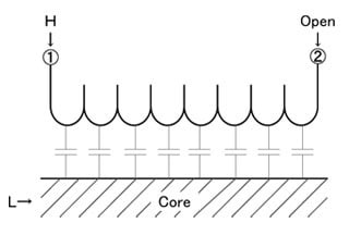
However, as shown in gray in Figure 1-1, the distributed capacitance exists in the coil. Because distributed capacitance exists, frequency and phase change with respect to ① in ②. And as a result, the measured value becomes inaccurate. In order to stabilize this, short ① and ② as shown in Figure 1-2
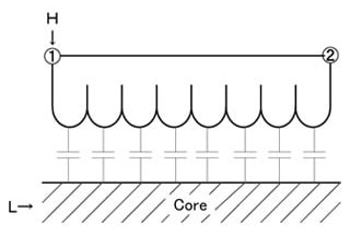
① and ② are in phase and the measurement result is stabilized.
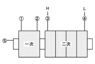
Ⅱ. Transformer test
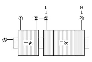
In the case of the transformer test, connect the primary coil ② and secondary coil ③, after that connect H (high voltage) ④ and L (return) ③.
Furthermore, it is better to adjust the measurement frequency to the actual use condition. In addition, the core may be grounded.
Generally, the high frequency transformer floats the core, the low frequency transformer is grounded and used. Please connect according to the actual use condition.
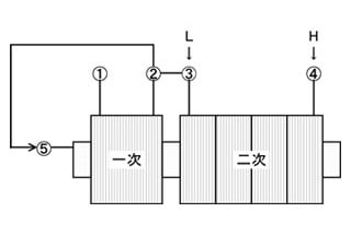
By the way, although the temporary side is separated in Figure 4, this is an unstable connection.

Because the both ends ① ② of the primary coil are floating, the potential between the primary coil and the secondary coil is not determined and the measured value becomes unstable.
It will become different from the actual use state. Perhaps ② and ③ are supposed to be connected in actual use state. Please connect ② and ③ as shown in Figure 2.
In Figure 5 H (high voltage) is connected to ③ on the side close to the primary coil, and L (return) is connected to ④.
In this connection, since high voltage is applied to the side close to the primary coil , the potential difference between the primary coil and the secondary coil becomes steep, resulting in a dangerous condition. Perhaps it is not the actual usage state.
In Figure 5, it is usually mostly a misconnection. Please check the actual use condition again.
- The corona discharge causes short destruction that has bad influence on a power switching circuit.
- Corona discharge animation
- Caution of corona discharge test of transformer and coil
- XT-330/XT-350 Tuning method
- XT-350 Discharge Rate
- Reason for not indicating of Quantity electric charge amount in high frequency corona discharge test (partial discharge test)
- XT-330/XT-350 a measurable range
- Corona discharge examination connection method of the motor
- Corona discharge examination connection method for the transformer