Technical informationXT-330/XT-350 Tuning method
XT-330, XT-350 tune the manual variable inductance and the impedance of the object to be measured by doing so, it outputs 10kVrms efficiently.
Tuning is important as it will result in 10kVrms output not being tuned.Variable inductance transformer inside the probe tuning step ① 700mH (tuning lamp ①)F
rom step ⑧ 86mH (tuning lamp ⑧) has stray capacitance 30pF.It is adjusted to the resonance frequency by the combined impedance of the impedance, the object to be measured and the impedance please.
The tuning when the test frequency is not specified by the basic tuning method is as follows It will be a procedure.
- Position the tuning lamp ④.
- Set the test frequency to 50kHz.
- Set the drive current 1 to 1.5A.
- Increase the test frequency by 1 kHz increment. (Leave the active lamp ON)
- At this time, pay attention to see if HV goes up.
- Try the lower test frequency from 50kHz.
- Also watch for HV not going up again.
- And when HV goes up, HV will fix to the highest test frequency.
- Turn the tuning knob to set the lowest drive current between ① – ⑧ lamps. There are times when HV goes down when minimizing the drive current, but do not worry.
- With this setting, turn the drive adjustment knob to raise the HV voltage to the test voltage.
The tuning when the test frequency is specified by the basic tuning method is as follows It will be a procedure.
- Set the test frequency.
- Position the tuning lamp ④.
- Set the drive current 1 to 1.5A.
- Turn the tuning knob to maximize HV. When the HV maximum is on the left of the lamp ①, it indicates that the resonance frequency is low, so the auxiliary inductance is set to, Please add and increase the resonance frequency and set the set frequency. Also, when the HV maximum is on the right of the lamp ⑧, it indicates that the resonance frequency is high, so the auxiliary capacitor Please add and lower the resonance frequency and set the set frequency. (If the drive current exceeds the 1 to 1.5A range during HV maximum adjustment, drive adjustment knob Please adjust to not exceed 1.5A by turning)
- There is a tuning point near HV maximum. Tune to minimize the drive current. Please turn the tuning knob to the left and right to check the tuning. (At this time HV will down, please do not mind)
- Turn the drive adjustment knob to raise the HV and measure the corona discharge start voltage. (When tuning is taken, the drive current is 5 A or less, but the drive current is large, Please tuning so that the current down when it becomes)
- When the drive current reaches 5 A or more, heat generation will be large, so please make a short test. Please test with the drive current where the temperature of the power amplifier does not exceed 90 degrees.
XT-330/XT-350 tuning design philosophy
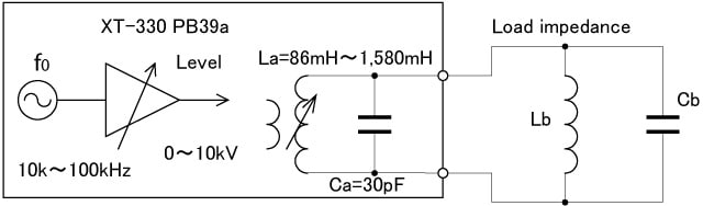
- The test frequency f0 can be set from 10kHz to 100kHz in steps of 1kHz.
- The output level can be continuously varied from 0 to 10kVrms.
- The output transformer La can be varied from 86mH to 700mH.
- The stray capacitance Ca of La of the output transformer is 30pF.
- Set the resonance frequency by output impedance La, Ca and load impedance Lb, Cb to f0 It outputs high voltage of 10kVrms by matching.
- The resonant frequency can be adjusted to the desired frequency by varying La and selecting Cb. (Refer to the measurable range diagram in another figure XT-330,XT-350)
- Load impedance is possible without Lb or without Cb. (Refer to the measurable range diagram in another figure XT-330,XT-350)
- Especially for Cb only measurement, high level measurement of 10kVrms, 700mA, 7kVA can be performed at 10kHz.
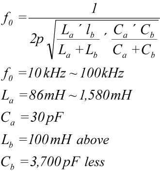
- The above resonance frequency f0 is as follows.
Other Technical information
- The corona discharge causes short destruction that has bad influence on a power switching circuit.
- Corona discharge animation
- Caution of corona discharge test of transformer and coil
- XT-330/XT-350 Tuning method
- XT-350 Discharge Rate
- Reason for not indicating of Quantity electric charge amount in high frequency corona discharge test (partial discharge test)
- XT-330/XT-350 a measurable range
- Corona discharge examination connection method of the motor
- Corona discharge examination connection method for the transformer